logo
أرسل رسالة
LINK-PP INT'L TECHNOLOGY CO., LIMITED
فئات المنتجات
شريكك المحترف والموثوق.
معلومات عنا
شريكك المحترف والموثوق.
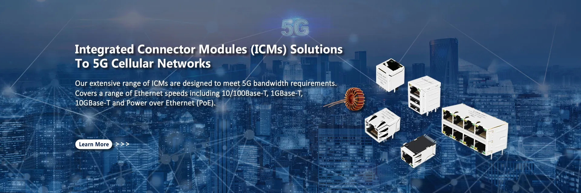
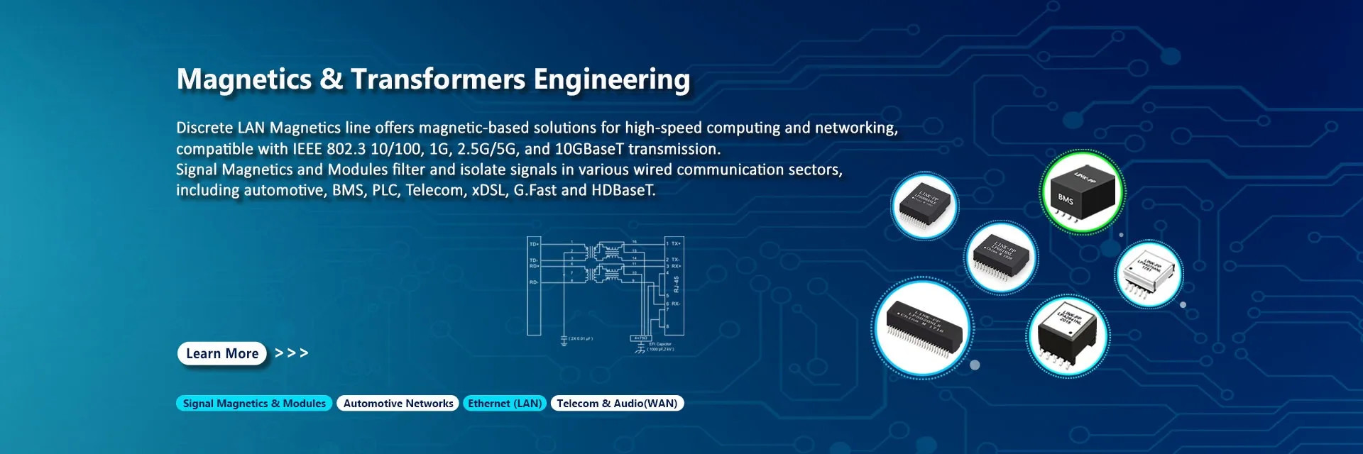
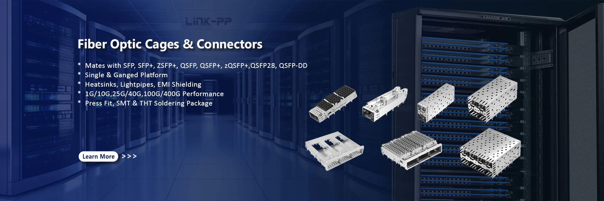
شركة LINK-PP International Technology Co., Limited، التي تأسست عام 1997، هي شركة تصنيع متكاملة رأسيًا متخصصة في المكونات المغناطيسية للإيثرنت وحلول الاتصال عالية السرعة حتى 10G. مع أكثر من 26 عامًا من الخبرة، تشمل منتجاتنا الأساسية مقابس RJ45 المعيارية، و MagJacks، والمغناطيسات المنفصلة، ومحولات الشبكة المحلية (LAN)، وأجهزة الإرسال والاستقبال الضوئية SFP/QSFP، وأقفاص ومقابس SFP/SFP+.تعمل LINK-PP في مرافق التشكيل والقولبة بالحقن والتجميع الآلي داخل الشركة، بدعم من ما يقرب من 600 موظف ومعدات إنتاج ...
يتعلم أكثر

0

سنة تأسيسها

0

مليون+
موظفين

0

مليون+
خدمة الزبائن

0

مليون+
المبيعات السنوية
الصين LINK-PP INT'L TECHNOLOGY CO., LIMITED جودة عالية
ختم الثقة ، فحص الائتمان ، RoSH وتقييم قدرة المورد. الشركة لديها نظام صارم لمراقبة الجودة ومختبر اختبار احترافي.
الصين LINK-PP INT'L TECHNOLOGY CO., LIMITED التنمية
فريق تصميم محترف داخلي و ورشة عمل الآلات المتقدمة يمكننا التعاون لتطوير المنتجات التي تحتاجها
الصين LINK-PP INT'L TECHNOLOGY CO., LIMITED التصنيع
آلات آلية متقدمة، نظام تحكم صارم للعملية. يمكننا تصنيع جميع المحطات الكهربائية أكثر من الطلب.
الصين LINK-PP INT'L TECHNOLOGY CO., LIMITED 100% خدمة
التعبئة السائبة والتعبئة الصغيرة المخصصة، FOB، CIF، DDU و DDP. دعونا نساعدك في إيجاد أفضل حل لكل مخاوفك

أهم المنتجات

شريكك المحترف والموثوق.
الحالات والأخبار
أحدث المواقع الساخنة.
محركات PoE Magjacks تدفع أنظمة مراقبة مدينة ذكية موثوقة
دراسة حالة: PoE Magjacks تقود أنظمة مراقبة مدينة ذكية موثوقة بينما تستمر البيئات الحضرية في تبنيتكنولوجيات المدن الذكية، أصبحت مراقبة الفيديو حجر الزاوية للسلامة العامة وإدارة حركة المرور.لا تتطلب كاميرات IP معتمدة على الذكاء الاصطناعي فقط نقل البيانات المستقر ولكن أيضًا توفير الطاقة الموثوق به في البيئات الخارجية الصعبة.   حل PoE Magjack واجه مزود حلول أمنية عالمية عدة عقبات عند التخطيط لنشر آلاف كاميرات مراقبة PTZ (Pan-Tilt-Zoom) في جميع أنحاء المدينة: بث الفيديو ذو النطاق العريض:مع تحليلات الذكاء الاصطناعي وجودة الفيديو 4K2.5G الاتصال بـ Base-T Ethernetكانت مطلوبة للقضاء على اختناقات الشبكة. طاقة موثوقة عبر إثنتر (PoE+):كل وحدة مطلوبةIEEE 802.3في الامتثال، وتوفر ما يصل إلى 30 واط لدعم محركات الكاميرا وأنظمة التدفئة المتكاملة. التسامح البيئي القوي:سيتم تعريض الأجهزة لدرجات حرارة من-40°C إلى +85°C، وكذلك التداخلات الكهربائية من البنية التحتية للطاقة القريبة. أدت النماذج الأولية باستخدام موصلات RJ45 القياسية إلى أداء غير مستقر ، معتدهور الإشارة تحت الحمل الكامل PoEوأخطاء البيانات المتكررة أثناء التشغيل عند درجات الحرارة العالية.   حل PoE Magjack لمعالجة هذه القضايا، قام فريق الهندسة بتكامل(بوك ماجاكس)مصممة2.5G Base-T و PoE+تطبيقات. بالمقارنة مع موصلات RJ45 التقليدية ، تجمع المقابس المغناطيسية بين المغناطيسية المتقدمة ، والدرع الأمثل ، ومعالجة PoE القوية ، مما يجعلها مثالية لشبكات المراقبة الذكية.  الميزات الرئيسية المشمولة:   سلامة الإشارة عالية التردد:تضمن المغناطيسية الداخلية المعدلة الحد الأدنى من فقدان الإدراج والإتصال المتقاطع لـ Ethernet متعدد الجيغابيت. أداء PoE + محسن:المحولات المدمجة مع الملفوفات المقاومة30W PoE + التسليمدون التدخل في نقل البيانات الصناعية الصلبة:مجموعة واسعة من درجات حرارة التشغيل و EMI الحماية تضمن الأداء المستقر في عمليات النشر في الهواء الطلق.   نتائج التنفيذ بعد اعتماد PoE Magjacks، حقق مشروع المراقبة تحسينات كبيرة: بيانات مستقرة خالية من الأخطاء:2بقيت روابط إثنر.5G موثوقة حتى تحت حمولة PoE + الكاملة. تثبيت أسرع:انخفاض حالات الفشل أثناء النشر، وتقليل عمليات استكشاف الأخطاء، والتأخير في الموقع. الموثوقية على المدى الطويلحافظ النظام على وقت تشغيل عال معتكاليف صيانة منخفضة، تعمل بسلاسة في جميع الظروف الجوية.   لماذا هي مهمة للمدن الذكية نجاح هذا المشروع يبرز أهميةاختيار مكونات الشبكة الخاصة بالتطبيقفي بيئات المدن الذكية حيث تكون الموثوقية حاسمةتوفر PoE Magjacks أساسًا مضادًا للمستقبلللمراقبة، وبنية تحتية إنترنت الأشياء، وأنظمة حركة المرور الذكية. لمزيد من التفاصيل حول موصلات PoE RJ45 والمقبضات المغناطيسية، قم بزيارةمُزود RJ45.
LPJ0017GENL رابط RJ45 مع مغناطيسية متكاملة لـ 10/100Base-T Ethernet
LPJ0017GENL رابط RJ45 مع مغناطيس 10/100Base-T   الطراز:LPJ0017GENL متوافق مع:إكس دبليو آر جي 1104 دي 1015-1، 13F-60GYDP2NL، MJF13T36L-KF06B3GY-0808، HR911157C، HR921157C     لمحة عامة عن المنتج الـLPJ0017GENLهو منفذ واحدرابط RJ45 مع مغناطيسية متكاملة 10/100Base-T، تم تطويرها وتصنيعها من قبلشركة لينك بي بي للتكنولوجيا الدولية المحدودةتم تصميم هذا النموذج لتلبية معايير IEEE802.3 ، ودمج كل من الواجهة المادية RJ45 والدوائر المغناطيسية (المحولات ، الخنق) المطلوبة للاتصال على Ethernet. مصممةمؤشرات LED مزدوجة(الأخضر والأصفر) وتركيب ثقب ، هذا المرفق المدمج والقوي يستخدم على نطاق واسع في معدات الشبكات SOHO ، LAN على لوحة الأم (LOM) تصاميم ،ومراقبين صناعيين.     الخصائص الرئيسية مغناطيسية متكاملة 10/100Base-Tتوفير مساحة PCB، والحد من عدد المكونات، وتبسيط تخطيط. مؤشرات LED مزدوجةالخضراء (565nm) لوضع الرابط، والصفراء (585nm) للإشارة إلى النشاط. الحماية المضمنة من EMIيضمن سلامة الإشارة في بيئات عالية التداخل. أجهزة الاتصال المصفوفة بالذهبيوفر مقاومة التآكل والقيادة المستمرة. متوافق مع RoHS و IEEE802.3صديقة للبيئة ومتوافقة مع البروتوكول للتطبيقات العالمية. التوافقمتوافق تماما مع نماذج من العلامات التجارية الرئيسية مثل XWRJ-1104D1015-1 و HR911157C.     المواصفات الكهربائية (@ 25°C) المعلم القيمة نسبة الدوران (± 2٪) TX = 1CT:1CT، RX = 1CT:1CT الحثية (OCL) 350μH MIN @ 100MHz / 0.1V ، 8mA DC Bias خسارة الإدراج - 1.0dB MAX (0.3 ‰ 100MHz) خسارة العائد -18 ديسيبل (130 ميه هرتز) ، -16 ديسيبل (40 ميه هرتز) ، -14 ديسيبل (50 ميه هرتز) ، -12 ديسيبل (6080 ميه هرتز) الحديث المتقاطع -45dB (30MHz) ، -40dB (60MHz) ، -35dB (100MHz) رفض الوضع المشترك -35dB (30MHz) ، -30dB (60MHz) ، -25dB (100MHz) التوتر العزلي للخلفية 1500Vrms درجة حرارة العمل 0°C إلى +70°C   مواصفات LED السمة المواصفات تكوين LED مزدوج: اليسار (الأخضر) ، اليمين (الأصفر) طول الموجة الأخضر: 565nm، الأصفر: 585nm الجهد الأمامي (VF) 1.8 ∙2.8 فولت @ 20 مآ التيار العكسي (IR) الحد الأقصى 10μA @ 5V   المواصفات الميكانيكية والمواد السمة المواصفات الأبعاد (ملم) W: 15.93 × H: 13.80 × D: 21.25 نوع التثبيت ثقب من خلال (THT) التوجيه المدخل الأمامي مواد السكن PBT الحرارية + 30% من ألياف الزجاج (UL94V-0) مواد الاتصال الفوسفور البرونز C5210R-EH (0.35mm سمك) مادة الدبوس النحاس C2680R-H (0.35mm سمك) مادة الدرع SUS 201-1/2H الفولاذ المقاوم للصدأ (0.2mm سمك) طلاء الذهب، 6 ميكرو بوصات دقيقة في منطقة الاتصال الحد الأقصى لحام الموجات 265 درجة مئوية لمدة 5 ثوان   التطبيقات الـLPJ0017GENLمثالية لمجموعة واسعة من الأجهزة التي تعمل على شبكة إيثيرنت، بما في ذلك: موديمات ADSL وموجهات SOHO لوحات الأم مع شبكة LAN متكاملة (LOM) محولات ووحدات إيثيرنت أجهزة تحكم Ethernet الصناعية محطات ومؤسسات نقاط البيع بوابات إنترنت الأشياء والأجهزة المتصلة نظم الأمن والمراقبة تصميمها المغناطيسي المتكامل يجعله مفيدًا بشكل خاص للبيئات المحدودة بالمساحة التي تتطلب تصميمًا مبسطًا وموثوقية عالية.     الامتثال متوافقة مع RoHS متوافق مع IEEE802.3     الاستنتاج الـLPJ0017GENLيقدم رابط RJ45 المتكامل مزيجا قويا من كفاءة الفضاء، والأداء الكهربائي، والامتثال. مع مغناطيسية مدمجة، واقية EMI، ومؤشرات LED،فهو يسهل تصميم أجهزة Ethernet مع تلبية المعايير الدوليةإن توافقه مع العديد من العلامات التجارية المعروفة يجعله بديلاً مرنًا لتنفيذ تطبيقات مختلفة.   هل تبحث عن رابط RJ45 موثوق به وذو أداء عالي؟LINK-PP ‬s LPJ0017GENLلمشروعك القادم الذي يتوافق مع إيثيرنت.
RJ45 Female Connector for Switch Board: Complete Selection Guide
When you search for an RJ45 female connector for a switch board, you are usually not looking for just a simple Ethernet socket—you are trying to solve a real hardware problem. Maybe a switch port stopped working, a connector needs replacement, or you are designing a new PCB and need a reliable Ethernet interface. In all of these cases, choosing the wrong RJ45 connector can lead to signal failure, compatibility issues, or even a non-functional device. At first glance, RJ45 connectors may look identical. However, in switch board applications, they vary significantly in footprint, pin layout, shielding, LED configuration, and whether they include integrated magnetics (MagJack). This is why many engineers and buyers run into the same issue: the connector fits physically, but the port still doesn’t work. This guide is designed to eliminate that confusion. Instead of treating RJ45 as a generic component, we break it down from a PCB-level and system-level perspective, helping you understand what actually matters when selecting or replacing a connector on a switch board. What You’ll Learn in This Guide By reading this article, you will be able to: Clearly understand the difference between a standard RJ45 jack and a MagJack Identify the correct RJ45 connector type for your switch board Avoid common mistakes that cause replacement failures Learn how to verify pinout, footprint, and compatibility Troubleshoot RJ45 port issues more effectively Whether you are a hardware engineer, network equipment manufacturer, or repair technician, this guide will help you make the right decision faster—and avoid costly trial-and-error. Let’s start by understanding what an RJ45 female connector for a switch board really is and why it’s more complex than it seems. H2 1. What Is an RJ45 Female Connector for a Switch Board? An RJ45 female connector for a switch board is the board-mounted Ethernet receptacle used on a PCB to connect a switch or network device to an Ethernet cable. In practice, the phrase usually refers to a modular jack or Ethernet jack that is mounted on the circuit board, often in a right-angle format, and sometimes with integrated magnetics. TE Connectivity describes RJ45 modular jacks as highly integrated Ethernet connectivity solutions that connect from the cable all the way to the physical layer, which is exactly why they are so common in switch and industrial networking designs. The most important point is that RJ45 female connector does not always mean the same thing as a simple “socket.” In many switch-board applications, the part is not just a plastic and metal receptacle. It may be a MagJack, meaning the modular jack includes magnetics inside the connector body. TE explicitly states that embedding magnetics within the jack improves EMI shielding, reduces board footprint, and supports compact, high-density applications. That difference matters because a switch board is usually not looking for a cosmetic connector. It needs the correct electrical and mechanical interface: pin arrangement, board orientation, shielding, footprint, and in many cases integrated magnetics and LED positions. A connector that looks right from the outside can still fail at the PCB level if the internal design does not match the board requirements. TE’s industrial Ethernet material also notes that integrated-magnetics jacks can simplify PCB design and remove an extra assembly step, which shows why the connector style is closely tied to board design. For readers searching this keyword, the real intent is usually one of three things: replace a damaged switch-board port, identify the correct jack for a new PCB design, or understand whether a standard RJ45 jack is enough. The answer depends on whether the board expects a simple mechanical jack or a full MagJack solution. H2 2. Why Switch Boards Use RJ45 Female Connectors Switch boards use RJ45 female connectors because Ethernet traffic must physically enter and leave the PCB through a standardized network interface. The connector is the gateway between the internal switching hardware and the outside Ethernet cable, so it must support the mechanical insertion cycle, maintain signal integrity, and survive repeated use. TE describes industrial RJ45 connectors as rectangular data connectors designed for Ethernet networking, and notes their role in industrial applications that require dependable connectivity. On a switch board, the RJ45 connector is not just an end point. It affects the entire signal path, EMI behavior, board layout, and serviceability. Integrated magnetics can help keep the analog portion of the circuit more contained and can improve EMI noise shielding. TE states that integrated magnetics offer a highly integrated solution from the cable to the physical layer and can improve EMI shielding while reducing board footprint. That is why compatibility matters more than appearance. Two connectors may both be sold as “RJ45,” but one may be shielded and through-hole, one may be SMT, one may have LED positions, and one may include the magnetics the board expects. Manufacturers offer modular jacks in different mounting styles and orientations, including right-angle and vertical, through-hole and SMT, which means the same functional interface can be physically very different on the PCB. For switch-board designers and repair teams, the connector choice affects installation time, reliability, and future troubleshooting. A poor match can create symptoms that look like an Ethernet chip failure, a firmware issue, or a cable problem, even when the actual fault is the wrong jack type or a footprint mismatch. That is why the best way to treat this part is as a precision board component, not a generic commodity socket. H2 3. RJ45 Female Connector Types: SMT, Through-Hole, Shielded, and MagJack RJ45 female connectors are not all the same, and the differences matter a lot on a switch board. A useful way to think about them is by mounting style, shielding, and whether magnetics are integrated. TE and Molex both show that modular jacks come in different form factors, including right-angle or vertical styles, and in both through-hole and SMT soldering versions. SMT RJ45 connectors are designed to be soldered directly onto the PCB surface. They are common in compact designs and automated assembly flows. The practical advantage is density and manufacturing efficiency, while the tradeoff is that the board layout and mechanical support must be carefully designed for the connector’s loads and solder profile. TE’s industrial solutions highlight reflow-capable parts, which is a major reason SMT-based options are used in modern assemblies. Through-hole RJ45 connectors use plated holes in the PCB and are often chosen when mechanical strength is a priority. For switch boards that will experience frequent plugging, board stress, or more demanding handling, through-hole designs can provide a more robust mechanical anchor. Market listings from major distributors show many right-angle through-hole shielded RJ45 options, which reflects how common this style remains in real board designs. Shielded RJ45 connectors add a metal shield around the jack area to help with EMI control and grounding. In networking hardware, shielding is often preferred when the system must maintain signal quality in electrically noisy environments. TE notes that integrated magnetics can improve EMI shielding, which is one reason shielded MagJack-style solutions are widely used in industrial Ethernet. MagJack connectors combine the RJ45 jack and magnetics into one part. This is often the best fit when the PCB expects integrated isolation and Ethernet magnetics near the port. TE repeatedly describes these as integrated-magnetics RJ45 connectors and says they can simplify PCB design by removing extra assembly steps. For switch boards, this category is often the most important because the magnetics are not optional in many Ethernet PHY implementations; they are part of the expected port architecture. The practical takeaway is simple: choose the connector type based on the board design, not just the cable interface name. An RJ45 label alone does not tell you whether the part is SMT or through-hole, shielded or unshielded, or a jack-only connector versus a MagJack. H2 4. How to Choose the Right RJ45 Connector for Your Switch Board Choosing the right RJ45 connector starts with the PCB, not the cable. The first thing to verify is the footprint, because the footprint defines the actual hole pattern, pad geometry, and mechanical tab positions on the board. Google’s Search Essentials emphasizes using the language people actually search for, and in the hardware world that often translates to matching the exact part characteristics users care about: footprint, mounting style, and pinout. Start with the mounting style. If the board was designed for through-hole, an SMT replacement may not be mechanically or electrically acceptable. If the board uses SMT, a through-hole part may simply not fit the solder and pad arrangement. Manufacturers offer both SMT and through-hole modular jacks, so the format is not interchangeable by default. Next, verify the pin layout and orientation. The same connector family can be offered in right-angle or vertical versions, and the tab direction, LED placement, and board-entry direction can differ. For replacement work, the jack must match not only the Ethernet function but also the physical geometry of the port opening and the location of nearby components. Then check whether the board needs integrated magnetics. TE’s product pages make clear that integrated magnetics are central to many RJ45 solutions, especially where EMI shielding, compactness, and reduced assembly steps matter. If the original design uses a MagJack, replacing it with a plain RJ45 jack can break the link even when the plug still fits mechanically. Also check LED support. Many switch ports use link/activity LEDs integrated into the connector body. If the new part has no LED channels or places them differently, the board may still function electrically but fail visually or physically align with the front panel. Distributor listings show that RJ45 modular jacks are commonly offered in LED and non-LED versions, which is a good reminder that these details are part of the real selection process. Finally, review shielding, speed target, and mechanical height. TE’s industrial RJ45 pages reference 10/100 Mbps and 1 Gbps support, and note that connector families can be designed for different Ethernet and EMC requirements. In other words, port performance is a system-level decision, but the connector still has to fit the intended electrical environment and enclosure constraints. A good sourcing rule is this: do not buy from the connector name alone. Compare the board drawing, the datasheet, the orientation, the shielding style, the magnetics requirement, and the LED arrangement before you commit to a replacement or a new design part. H2 5. Common Compatibility Problems and Why RJ45 Replacements Fail The most common reason an RJ45 replacement fails is that the buyer treats every RJ45 jack as interchangeable. In reality, the connector is defined by more than the front opening. It also includes the footprint, shield design, pin arrangement, magnetics, and sometimes even the soldering process the board expects. TE’s documentation shows a broad family of RJ45 connectors that differ by style and integration level, which is exactly why compatibility errors are so common. A classic mistake is using a plain RJ45 jack where the original board used a MagJack. TE states that integrated magnetics are built into certain RJ45 jacks and that those parts serve as a highly integrated connectivity solution. If the system expects magnetics in the connector and they are missing, the port can fail to link even though the plug fits physically. Another common issue is a footprint mismatch. Through-hole and SMT parts are not just packaging variations; they require different PCB land patterns and mechanical support. If the replacement part has slightly different tab spacing, lead length, or shield post geometry, it may look close enough to fit but still be wrong for the board. Manufacturer listings clearly separate right-angle through-hole and SMT options because these are distinct implementation choices, not cosmetic ones. LED mismatch is another failure point. A replacement jack may function electrically but omit the LED positions used by the original board or place the indicators in a different orientation. For a switch board, that can create confusion during testing because the port may be live while the front-panel indication remains dark or misaligned. The variety of LED and non-LED modular jacks offered in the market shows how often this matters in real hardware. A subtler failure happens when the installer assumes that any RJ45 port with continuity should work. But integrated magnetics change what “normal” looks like during testing, and a direct continuity check can be misleading if the board design includes transformer isolation. That is why troubleshooting must consider the full port architecture, not just the connector shell. The best defense against replacement failure is to verify the part number against the original board design, not against a generic product listing. If the old connector included magnetics, shield features, LEDs, or a specific right-angle footprint, the new one must match those attributes exactly or the repair may never work reliably. H2 6. RJ45 Female Connector Pinout and PCB Footprint Basics The pinout and PCB footprint are the two most important technical references when sourcing or replacing an RJ45 female connector for a switch board. The pinout determines how the connector’s internal contacts map to the Ethernet circuitry, while the footprint determines where and how the part physically mounts on the board. Manufacturers offer many modular jack variants, which is why pinout and footprint must be checked from the datasheet rather than assumed from the connector name. A useful way to think about the footprint is that it is the board-level contract between the connector and the PCB. It sets the placement of the contacts, shield tabs, hold-down features, and board-edge clearance. A mismatch can produce soldering defects, mechanical stress, or a jack that fits the hole pattern but sits too high, too low, or slightly misaligned with the faceplate. TE’s industrial pages and distributor product listings show how many RJ45 families exist specifically because physical implementation details matter. The pinout issue becomes even more important when the part is a MagJack. In that case, the jack is not just passing the cable pairs through; it is also accommodating the integrated magnetics that the Ethernet PHY expects as part of the interface path. TE describes these parts as integrated solutions from the cable to the physical layer, which is why their internal architecture matters to the entire link. For engineers and repair teams, the safest checklist is simple. Confirm the board drawing, identify whether the original part is shielded, confirm whether the design uses integrated magnetics, verify the mounting style, and check whether the port includes LEDs or special tab orientation. Those are the kinds of details that separate a reliable replacement from an expensive second failure. When designing a new board, it is also wise to think ahead about manufacturability. TE highlights reflow-capable, industrial Ethernet jacks that simplify assembly, and Molex shows modular jacks in multiple orientations and soldering styles. That variety reflects a larger design truth: the footprint is not just a drawing detail; it is part of the production strategy. H2 7. How to Troubleshoot a Switch Board RJ45 Port That Does Not Work When a switch-board RJ45 port fails, the connector is only one possible cause. A port can fail because of solder defects, footprint mismatch, missing magnetics, damaged magnetics, PCB trace issues, or problems outside the connector entirely. TE’s industrial RJ45 material makes it clear that these parts can be highly integrated, which means troubleshooting must look at the whole port path rather than only the plastic jack on the front panel. Start with the obvious mechanical checks. Inspect the jack for bent contacts, cracked solder joints, missing shield tabs, and board damage around the anchor points. Through-hole and SMT connectors are stressed differently, and a visually acceptable joint can still be electrically weak if the part has moved during rework or if the footprint was not matched correctly. Manufacturer catalogs distinguish these mounting styles because the mechanical behavior is not the same. Next, verify the cable and link behavior. If the port does not link, try a known-good cable, a known-good switch peer, and a known-good endpoint. Because many RJ45 switch-board connectors include magnetics, link failure does not necessarily mean the RJ45 shell is broken. The issue may be in the integrated magnetic path or in the surrounding Ethernet circuit. TE notes that integrated magnetics improve EMI shielding and are part of the electrical solution, not just the mechanical one. Be careful with continuity testing. A simple buzzer test can create confusion when the port includes magnetics, because those transformer elements are meant to isolate the circuit in ways that do not behave like direct wire continuity. In other words, a lack of continuity does not always mean a failure, and a simple continuity reading does not always prove the port is healthy. The architecture of an integrated RJ45 jack matters to how you interpret the test result. If the port still fails after mechanical and link checks, compare the replacement connector to the original part number and board drawing again. A wrong pinout, missing LED path, or alternate shield design can look similar in the hand but fail on the board. This is why the most reliable troubleshooting strategy is to treat the connector as a matched system component rather than a standalone socket. H2 8. Best Practices for Selecting a Reliable RJ45 Connector Supplier For B2B buyers and engineering teams, supplier selection should focus on documentation quality, part consistency, and compatibility support. Google’s Search guidance says helpful content should satisfy the user’s needs first, and that same principle applies to sourcing hardware: the supplier should make it easy to verify the right part before purchase. The first best practice is to ask for complete technical data. You should be able to confirm the footprint, mounting style, shielding, LED arrangement, integrated magnetics, height, and orientation from the documentation. TE’s industrial RJ45 pages and product listings demonstrate how manufacturers present these distinctions because they are essential to correct selection. The second best practice is to request samples before volume purchasing. Even when the part number seems correct, a sample run lets you validate insertion depth, faceplate alignment, solderability, and link stability on the real PCB. TE’s site prominently supports product comparison, samples, and technical resources, which reflects the reality that connector selection often requires pre-production verification. The third best practice is to confirm assembly compatibility. If your production process uses reflow soldering, the connector must be rated for it. TE specifically calls out reflow-capable industrial Ethernet jacks and notes that integrated magnetics can simplify PCB design and assembly. That matters because a connector that is functionally correct but process-incompatible can still create production problems. The fourth best practice is to use a supplier that can support cross-reference and substitution decisions. In connector sourcing, replacement usually means matching an existing board layout, not selecting a fresh design from scratch. A good supplier should help you determine whether a candidate part is truly equivalent or only visually similar. TE’s product ecosystem includes cross-reference and comparison tools, which underscores how important part matching is in this category. Finally, prioritize suppliers who can clearly explain the difference between a simple RJ45 jack and an integrated-magnetics solution. That kind of technical support reduces return rates, saves engineering time, and prevents the exact kind of mismatch that makes switch-board repairs fail. H2 9. FAQ About RJ45 Female Connector for Switch Board Is RJ45 female connector the same as a MagJack? No. A MagJack is an RJ45 modular jack with integrated magnetics inside the connector body. TE describes this as an integrated solution that combines the jack and magnetics, which is why it is not the same as a plain RJ45 receptacle. Can any RJ45 jack fit a switch board? No. RJ45 jacks vary by mounting style, footprint, orientation, shielding, LED support, and whether they include magnetics. Manufacturers offer many versions, so the correct replacement must match the PCB design, not just the port shape. How do I match an RJ45 footprint? Start with the original board drawing or the old part datasheet, then verify mounting style, pad layout, shield tabs, board-edge position, and height. This is the safest way to avoid a part that fits visually but fails mechanically or electrically. Why does my replaced port still not work? The most common causes are wrong footprint, missing magnetics, LED mismatch, bad solder joints, or using a plain jack where the board expected an integrated-magnetics connector. Because integrated RJ45 solutions affect the full signal path, the failure may not be visible from the front of the board. What is the safest first check before ordering a replacement? Confirm whether the original part was a simple RJ45 jack or a MagJack, then match the exact mounting style and footprint. That single step eliminates many of the most expensive compatibility mistakes. H2 10. Conclusion: How to Choose the Right RJ45 Female Connector The right RJ45 female connector for a switch board is the one that matches the board’s mechanical layout, electrical expectations, and assembly process. In most real-world cases, the decision comes down to a few core checks: whether the board needs a plain jack or a MagJack, whether the mount is SMT or through-hole, whether the connector is shielded, whether LED positions matter, and whether the footprint truly matches the PCB. TE and other major connector manufacturers show that these are not minor variations; they are core product distinctions that affect function, EMI behavior, and manufacturability. For SEO and GEO purposes, this topic performs best when the page answers the technical question immediately, compares the connector types clearly, and includes FAQ-style answers that can be quoted cleanly. That aligns with Google’s guidance on people-first content, with its Search Essentials recommendation to use the terms people search for in prominent locations, and with the way structured data can help Google understand the page. Google also notes that AI features surface relevant links and that unique, valuable content matters across both classic results and AI experiences. For buyers, engineers, and repair teams, the most practical next step is simple: match the connector to the board, not the other way around. If you verify the footprint, magnetics, shielding, LED layout, and mounting style before ordering, you avoid the most common replacement failures and get a much better chance of first-time success.

2026

04/16

دليل تصميم وتركيب قفص SFP
  مقدمة: لماذا تصميم قفص SFP يؤثر مباشرة على موثوقية النظام   وقفص SFP(فاكتور الشكل الصغير القفص القابل للشحن)هي علبة معدنية مثبتة على لوحة PCB التي:   يوفر الدعم الميكانيكي للمستقبلات القابلة للتوصيل يضمن المواءمة مع اللوحة الأمامية (البيزل) يخلق مسار موصل لحماية EMI يدعم تدفق الهواء الحراري من خلال الهياكل التهوية   يجب أن تعمل أقفاص SFP كجزء مننظام كهروميكانيكي متكامل بالكامل، وليس كمكونات مستقلة.   في أنظمة شبكات عالية السرعة الحديثة،مجموعات أقفاص SFPغالبًا ما يتم التعامل معها على أنها مكونات ميكانيكية سلبية.دور حاسم في الاستقرار الميكانيكيإم إيهالحماية، والأداء الحراري، والموثوقية على المدى الطويل. التصميم أو التثبيت غير السليم لقفص SFP يمكن أن يؤدي إلى:   فشل الامتثال لـ EMI خلل في محاذاة وحدات الإدخال النقاط الساخنة الحرارية عدم استمرارية الترسيم التآكل الميكانيكي المبكر   هذا الدليل يلخصالاحتياطات الهندسية الحاسمةلتصميم قفص SFP، ودمج PCB، وتجميع على أساس تحديات النشر في العالم الحقيقي ومواصفات الصناعة.     1. التحكم الصارم في درجة حرارة التشغيل   أقفاص SFP والمكونات المرتبطة بها مصممة عادة للعمل داخل-40°C إلى 85°C.   التعرض لدرجة حرارة مفرطة أثناء:   التجميع تنظيف التدفق التخزين   قد يسبب تشوه:   مكونات بلاستيكية أنابيب الضوء هياكل الاتصال دعامات ميكانيكية   هذا يؤثر مباشرةأداء الإدراج ، وقوة الاحتفاظ ، وفعالية الدرع EMI.     2التحقق من التوافق المادي مسبقاً   وتشمل مواد قفص SFP النموذجية:   سبيكة الفضة والنيكل المقوى بالنيكل (بنية القفص) البوليكربونات (UL 94-V-0) للأنابيب الخفيفة   أثناء التصميم واختيار العملية:   تجنب التعرض لدرجات حرارة عالية تتجاوز حدود المادة تجنب المذيبات العدوانية ضمان التوافق مع مواد التنظيف   يمكن أن يؤدي تدهور المواد إلىالشقوق أو الهشاشة أو فشل في الموثوقية على المدى الطويل.     3التخزين غير السليم يؤدي إلى التشوه والتلوث   أقفاص SFPيجب أن تبقى فيالتعبئة الأصلية حتى التجميع.   التعامل غير السليم قد يسبب:   تشويه خطوط الاتصال ثني ذيول الأرض تلف أعمدة التثبيت تلوث السطح الذي يؤثر على الموصلات   اتبعFIFO (أول دخول، أول خروج)ممارسات الجرد لمنع مشاكل الأداء المتعلقة بالشيخوخة والتلوث.     4تجنب التعرض للبيئات الكيميائية المآكلة   لا يجوز تعريض مجموعات قفص SFP للمواد الكيميائية التي يمكن أن تسببتشق التآكل بالتوتروخاصة:   القليات الأمونيا الكربونات أمينات مركبات الكبريت النترات الفوسفات الترترات   هذه المواد يمكن أن تتحلل:   واجهات الاتصال الهياكل الأرضية أعمدة تركيب   مما أدى إلىعدم استقرار الاتصال الكهربائي، فشل الأرض، وإضعاف الهيكل.     5يجب أن تلبي سماكة PCB متطلبات التصميم   المواد الموصى بها لـ PCB:   FR-4 مجموعة العشر   متطلبات الحد الأدنى للسمك:   ≥ 1.57 ملم (تصاميم قياسية أو ذات جانب واحد) ≥ 3.00 ملم (من بطن إلى بطن أو تصاميم مكدسة)   السماكة غير الكافية لـ PCB قد تؤدي إلى:   عدم الاستقرار الميكانيكي بعد الضغط الإجهاد غير الطبيعي على الدبابيس المتوافقة عمر دورة الإدراج المختصر زيادة في صفحة اللوحة     6مسطحة الـ (بي سي بي) أمر حاسم   الحد الأقصى للتسامح في قوس PCB يقتصر عادة على≤ 0.08 ملم.   التشوه المفرط قد يسبب:   الحمل غير المتساوي على الدبابيس المتوافقة مقاعد القفص غير الكاملة فجوات معركة غير طبيعية خطأ في التوجيه أثناء إدخال الوحدة   هذه المسألة حاسمة بشكل خاص فيتكوينات متعددة الموانئ عالية الكثافة.     7يجب أن يكون حجم الحفرة وموقعها دقيقاً       يجب أن تكون جميع ثقوب التثبيت:   محفرة ومطلية حسب المواصفات موقع دقيق وفقًا لمتطلبات تخطيط PCB   المشاكل الشائعة الناجمة عن ضعف دقة الثقب:   إبر منحنية أو تالفة صعوبة إدخال المطبعة ضعف أداء اللحام أو الأرض انخفاض الاحتفاظ الميكانيكي   دقة الحفر أكثر أهمية من التوافق البسيط، لأنها تؤثر بشكل مباشر على أداء مؤسسة EMI ووحدة هيكلية.     8يجب أن يتم التحكم في سمك الحاجز وتصميم القطع   سمك الحاجز الموصى به:0.8 ملم إلى 2.6 ملم   يجب أن يكون الحاجز:   السماح بتثبيت القفص بشكل صحيح تجنب التدخل مع قفل الوحدة ضغط الألواح الأرضية لوحة بشكل صحيح الحفاظ على الضغط المناسب على غطاء EMI   التصميم الخاطئ للشاشة يمكن أن يؤدي إلى:   خلل في قيادة القفل عدم كفاية درع EMI التداخل الميكانيكي مع المكونات المجاورة عمق إدراج الوحدة غير متسق     9يجب أن يتم التصميم المشترك لـ PCB و Bezel   يجب تقييم موقع PCB والحاجز معًا لضمان:   التشغيل السليم لقفل الوحدة الضغط الصحيح للربيعات الأرضية أو الصمامات محاذاة ميكانيكية مستقرة   العديد من إخفاقات الميدان لا تسببها أقفاص معيبة، ولكنخلل في التواء بين PCB والحاجز وتجميع القفص.     10. موازنة جميع المسامير المتوافقة في وقت واحد أثناء التثبيت   أثناء التجميع:   يجب أن تتماشى جميع الدبابيس المتوافقة مع ثقوب PCB في نفس الوقت تجنب إدخال جزئي أو تدريجي   إذا لم يتم ذلك، فقد يؤدي ذلك إلى:   إلتواء أو ثني الدبابيس قوة إدخال غير طبيعية قضايا موثوقية الاتصال على المدى الطويل   هذا واحد منأخطاء التجميع الأكثر شيوعًافي الإنتاج.     11التحكم في قوة الضغط والارتفاع في المقعد   يجب أن يتبع تثبيت الجهاز المضغوط ظروفًا خاضعة للرقابة:   سرعة الإدراج: ~ 50 ملم/دقيقة توزيع قوة موحد   الأهم من ذلكيجب تعيين ارتفاع الإغلاق بشكل صحيح.   نظرة حاسمة:   الحد الأقصى للإجهاد يحدث قبل الجلوس بالكامل وليس في النهاية.   القيادة الزائدة قد تسبب أضرار دائمة:   الدبوسات المتوافقة هيكل القفص ملامح الترسيم     12التحقق من فجوة الصدمة إلى PCB بعد التجميع   بعد التثبيت، تحقق من: الحد الأقصى للفجوة بين الجهاز الوقائي وPCB ≤0.10 ملم   الفجوة المفرطة تشير إلى عدم اكتمال المقاعد وقد تؤدي إلى:   شعور ضعيف بإدخال عدم استمرارية الترسيم عدم الاستقرار الميكانيكي انخفاض في الموثوقية على المدى الطويل     13أداء EMI يعتمد على تكامل النظام   فعالية الدرع الإي إم يعتمد على النظام بأكمله، وليس فقط القفص.   تأكد من:   يتم ضغط الينابيع الأرضية لوحة بشكل صحيح صمامات EMI تعمل بشكل كامل وجود مسار الأرضية المستمرة بين القفص، محيط، وPCB   الفشل في أي من هذه المجالات يمكن أن يؤدي إلىفشل اختبار EMI، حتى لو كان القفص نفسه يستوفي المواصفات.     14التنظيف يجب أن يُراقب بعناية   بعد اللحام أو إعادة العمل:   إزالة كل تدفق والبقايا تأكد من أن واجهات الاتصال تبقى نظيفة   حتىبقايا معجون اللحام غير النظيفيمكن أن:   تعمل كعازلات كهربائية تحسين أداء الأرض تقليل فعالية الدرع EMI     15. استخدموا مواد تنظيف متوافقة فقط   يجب أن تكون مواد التنظيف متوافقة مع كل من:   الهياكل المعدنية مكونات بلاستيكية   تجنب:   ثلاثي الكلور إيثيلين كلوريد الميثيلين دائماً اتبعمبادئ توجيهية MSDS.   الممارسة الموصى بها:   تجفيف الهواء تجنب تجاوز حدود الحرارة أثناء التجفيف     16يجب استبدال المكونات المتضررة   لا تعيد استخدام أو إصلاح أقفاص SFP المتضررة.   يجب استبدالها على الفور إذا لوحظ أي من الآتي:   إبر منحنية هيكل قفص مشوه الاتصالات الأرضية المتضررة خلل في القفل ربيعات التربة المشوهة   المكونات المتضررة يمكن أن تؤثر بشدةموثوقية، أداء EMI، والثبات الميكانيكي، وخاصة في الأنظمة عالية الكثافة.     الاستنتاج: موثوقية قفص SFP تعتمد على التحكم على مستوى النظام       يتم تحديد أداء قفص SFP ليس فقط من خلال جودة المكونات ، ولكن من خلال مدى التحكم في العوامل التالية:   تصميم الـ PCB ودقة محاذاة البيزل عملية الضغط استمرارية الترسيم الحرارة تنظيف وتوافق المواد   المعلومات الرئيسية   تتطلب أداء قفص SFP الموثوق به التحكم الدقيق في تخطيط PCB وتحقيق محاذاة الحاجز وظروف الضغط والتركيب والتواصل في الأرض ، حيث تحدد هذه العوامل بشكل جماعي درع EMI ،الاستقرار الميكانيكي، وموثوقية النظام على المدى الطويل.  

2026

04/09

الدليل الكامل لأقفاص SFP: الأنواع والتصميم والاختيار
  في أنظمة الشبكات عالية السرعة، يركز المهندسون غالبًا على أجهزة الإرسال والاستقبال، وسلامة الإشارة، وتصميم ثنائي الفينيل متعدد الكلور - لكنهم يتجاهلون عنصرًا مهمًا واحدًا:قفص SFP. على الرغم من أنه قد يبدو وكأنه حاوية معدنية بسيطة، إلا أن قفص SFP يلعب دورًا مركزيًا في ضمان الأداء الموثوق به، والاستقرار الميكانيكي، والامتثال الكهرومغناطيسي في تطبيقات العالم الحقيقي.   قفص SFP هوواجهة ميكانيكية من جانب المضيفيسمح للوحدات الصغيرة القابلة للتوصيل (SFP) بالاتصال بشكل آمن بلوحة PCB ومواءمتها بدقة مع اللوحة الأمامية (الإطار). وبعيدًا عن إدخال الوحدة الأساسية، فهو يؤثر بشكل مباشرحماية EMI، وتبديد الحرارة، وسلامة التأريض، والمتانة طويلة الأمد. يمكن أن يؤدي القفص الذي تم اختياره بشكل سيئ أو المدمج بشكل غير صحيح إلى مشكلات مثل تداخل الإشارة، أو ارتفاع درجة الحرارة، أو اختلال الوحدة، أو حتى فشل المنتج أثناء اختبار EMC.   مع استمرار معدلات البيانات في التوسع من1G إلى 10G، 25G، وما بعدهاومع زيادة كثافة المنافذ في المحولات وأجهزة التوجيه والخوادم، زادت أهمية تصميم قفص SFP بشكل ملحوظ. التصاميم الحديثة يجب أن تكون متوازنةتخطيطات عالية الكثافة، وتدفق هواء فعال، واحتواء EMI قوي، وقابلية للتصنيع- وكلها تتأثر ببنية القفص وتكوينه.   تم تصميم هذا الدليل لمهندسي التصميم ومطوري الأجهزة والمشترين الفنيينالذين يحتاجون إلى أكثر من تعريف أساسي. من خلال التوافق مع التحديات الهندسية الواقعية وهدف البحث، ستساعدك هذه المقالة على: فهمالوظيفة والهيكلمن أقفاص SFP قارن مختلفةأنواع وعوامل الشكل تعلم الاعتبارات الرئيسية لتصميم EMI والحراري وثنائي الفينيل متعدد الكلور تجنب الشائععيوب التصميم والتصنيع حدد قفص SFP المناسب لتطبيقك المحدد سواء كنت تقوم بتصميم محول عالي الكثافة، أو تحسين اللوحة الأم للخادم، أو توفير مكونات للإنتاج، فإن هذا الدليل الكامل سيوفر لك الرؤى العملية اللازمة لاتخاذ قرارات مستنيرة.     1. ما هو قفص SFP؟       قفص SFP هو العلبة الميكانيكية التي تستقبل جهاز إرسال واستقبال قابل للتوصيل من عائلة SFP أو وحدة نحاسية وتثبته في موضعه على اللوحة الأمامية. في وثائق البائع، تخدم مجموعة القفص أيضًا واجهة اللوحة، مع ميزات التأريض، وميزات الاحتفاظ، وتفاعل الإطار المدمج في التصميم.   بالنسبة للمهندسين، هذا يعني أن تأثير القفص أكبر بكثير من مجرد التركيب الميكانيكي. إنه يؤثر على الاحتفاظ بالوحدة، وقمع EMI، وتدفق الهواء، وعملية التجميع، وما إذا كان يمكن تصنيع المنفذ على نطاق واسع دون أي مشاكل في إعادة العمل. تنص شركة Molex صراحةً على أن مجموعات القفص الخاصة بها توفر قمع EMI وفتحات تهوية حرارية وأصابع أرضية للوحة أو حشية موصلة.     2. أنواع أقفاص SFP وعوامل الشكل       أقفاص SFP تأتي في عدة تخطيطات عملية. تسرد Molex أقفاصًا أحادية المنفذ وتكوينات مجمعة 1x2 و1x4 و2x2 و2x4 و1x6، بينما تقوم TE بتجميع محفظتها في SFP وSFP+ وSFP28 وSFP56 ومكدسة من البطن إلى البطن ومتغيرات أخرى عالية الكثافة. تشير TE أيضًا إلى أن المحفظة تغطي احتياجات النظام المختلفة مثل مساحة PCB والسرعة وعدد القنوات وكثافة المنافذ.   أسلوب التركيب هو تقسيم رئيسي آخر. تقدم شركة Molex أقفاصًا أحادية المنفذ بإصدارات ملائمة للضغط، وعمود لحام، وPCI بدرجة واحدة، بينما تتوفر الأقفاص ذات العصابات في إصدارات مناسبة للضغط. تشير TE أيضًا إلى أقفاص لتطبيقات بطاقة PCI وتقول إن محفظتها تشتمل على أقفاص أحادية المنفذ، ومجمعة، ومكدسة، ومن البطن إلى البطن.   يعتمد نوع القفص المناسب على اللوحة واللوحة الأمامية. إذا كنت تقوم بتحسين الكثافة، فإن الخيارات من البطن إلى البطن والخيارات المكدسة مهمة. إذا كنت تعمل على تحسين مرونة التجميع، فإن خيارات الضغط ووظيفة اللحام مهمة. إذا كنت بحاجة إلى التعرف على اللوحة الأمامية أو سهولة الخدمة، فإن متغيرات الأنابيب الخفيفة تصبح مهمة. تدرج شركة Molex بشكل صريح أنابيب الضوء الاختيارية في مجموعات القفص الخاصة بها، وتدرج TE خيارات الأنابيب الخفيفة في مجموعة الأداء العالي.     3. الهيكل الميكانيكي لقفص SFP     من السهل التغاضي عن الميزات الميكانيكية الرئيسية حتى تفشل. تصف موليكس مزلاج القفل، وزنبرك الإطلاق، وملامسات الذيل المتوافقة، وأصابع زنبركية اللوحة، وفتحات التهوية الحرارية كأجزاء أساسية من هيكل القفص. هذه الأجزاء هي التي تجعل عملية الإدراج والاحتفاظ والتحرير والتأريض والجلوس تعمل في منتج حقيقي.   يقوم المزلاج بتثبيت الوحدة في مكانها، بينما يساعد زنبرك الإطلاق على تحريرها. تقوم الذيول المتوافقة أو الأرجل القابلة للضغط بتثبيت القفص بلوحة PCB، وتتفاعل النوابض الأرضية للوحة أو الحشية الموصلة مع الإطار لدعم قمع التداخل الكهرومغناطيسي. ولهذا السبب لا يمكن التعامل مع الأبعاد على مستوى اللوحة والإطار كتفاصيل ثانوية.     4. اعتبارات تصميم EMI وEMC     يعد EMI أحد الأسباب الرئيسية وراء أهمية تصميم قفص SFP. تقول TE إن محفظة SFP تركز على منطقة لوحة المزلاج لتقليل EMI وتجنب تدهور أداء الدائرة، وتوفر إصدارات EMI الربيعية والحشية المرنة EMI لتلبية متطلبات النظام. تنص TE أيضًا على أن تصميمات SFP+ تستخدم نوابض EMI محسّنة وخيارات الحشيات المرنة لاحتواء أقوى.   موليكس مباشر بنفس القدر: توفر مجموعات القفص قمع EMI من خلال أصابع اللوحة الأرضية أو حشية موصلة، ويجب أن يضغط الإطار على تلك الميزات لإنشاء الاتصال الأرضي الكهربائي الضروري. من الناحية العملية، يعني هذا أن الضغط من القفص إلى الإطار، وتصميم القطع، والتباعد بين المنافذ المجاورة كلها جزء من نجاح EMC.   بالنسبة لمهندس التصميم، فإن الاستنتاج بسيط: إذا كان مسار التأريض ضعيفًا، أو كانت منطقة المزلاج محمية بشكل سيئ، أو أن الإطار لا يضغط الزنبرك أو الحشية بشكل صحيح، فقد ينهار أداء EMI حتى لو كانت الوحدة نفسها متوافقة.     5. الإدارة الحرارية لأقفاص SFP     يصبح الأداء الحراري أكثر أهمية مع ارتفاع سرعات المنافذ وكثافة المنافذ. تقول TE إن محفظة SFP الخاصة بها تتضمن خيارات المشتت الحراري، وتسلط مواد SFP+ الخاصة بها الضوء على أداء حراري أكبر، وتبديد حرارة محسّن، وجدران جانبية محسّنة وفواصل رأسية كجزء من استراتيجية التصميم.   تقوم موليكس أيضًا ببناء فتحات تهوية حرارية في مجموعات القفص، مما يساعد على تدفق الهواء وتخفيف الحرارة. في تصميمات المحولات أو أجهزة التوجيه الكثيفة، لا يكون السؤال الحراري الحقيقي هو ما إذا كانت الوحدة مناسبة أم لا، ولكن ما إذا كان تخطيط اللوحة الأمامية يسمح بهامش تبريد كافٍ للكثافة المختارة ومستوى الطاقة.     6. تخطيط ثنائي الفينيل متعدد الكلور وتكامل الحافة     من الممكن أن يفشل القفص الذي يبدو صحيحًا في التصميم بمساعدة الكمبيوتر (CAD) إذا كانت العلاقة بين الإطار وثنائي الفينيل متعدد الكلور خاطئة. تحدد شركة Molex نطاق سمك الإطار من 0.8 مم إلى 2.6 مم وتنص على أن فتحة الإطار يجب أن تسمح بالتركيب المناسب أثناء ضغط النوابض الأرضية للوحة أو الحشية لقمع التداخل الكهرومغناطيسي.   تحذر شركة Molex أيضًا من ضرورة وضع الإطار وثنائي الفينيل متعدد الكلور لتجنب التداخل مع مزلاج قفل الوحدة وللحفاظ على الوظيفة المناسبة للينابيع الأرضية أو الحشية. وهذا يعني أن رسم اللوحة الأمامية، وتكديس اللوحة، وبصمة القفص يجب التعامل معها على أنها مشكلة تصميم واحدة، وليس ثلاث مشاكل منفصلة.   تعد مذكرة محفظة TE مفيدة أيضًا هنا: يعتمد اختيار القفص على مساحة PCB، والسرعة، وعدد القنوات، وكثافة المنفذ. بالنسبة لتخطيط التخطيط، هذا يعني أنه يجب تحديد عائلة القفص جنبًا إلى جنب مع إستراتيجية اللوحة الأمامية وليس بعد قفل PCB بالفعل.     7. تجميع قفص SFP وإرشادات العملية   يجب أن تؤثر طريقة التصنيع على اختيار القفص منذ البداية. تقدم شركة Molex إصدارات ملائمة للضغط، وأخرى لحام، وPCI للأقفاص ذات المنفذ الواحد، وتقول إن الأقفاص مصممة لتناسب مختلف سماكات اللوحة وعمليات التجميع. ويلاحظ أيضًا أن ذيول الضغط تدعم التطبيقات من البطن إلى البطن من أجل استخدام أفضل لعقارات ثنائي الفينيل متعدد الكلور.   تعليمات التجميع مهمة بقدر رقم الجزء. تحدد شركة Molex التسجيل الدقيق للدبابيس المتوافقة، وتحذر من الإفراط في تشغيل مجموعة الموصل، وتلاحظ أنه يجب التحكم في ارتفاع المقعد وارتفاع الإغلاق حتى يجلس القفص بشكل صحيح دون تشويه الميزات المهمة.   بالنسبة لمهندسي الإنتاج، هذا يعني أن التعامل والتركيب وإعداد الأدوات هي جزء من قصة الأداء الكهربائي. من الممكن أن يفشل القفص الصحيح تقنيًا على الورق إذا كانت قوة الإدخال أو عمق الجلوس أو تسجيل الدبوس غير متناسقة على الخط.     8. توافق ومعايير قفص SFP     تذكر TE أن محفظة SFP الخاصة بها تتوافق مع مواصفات SFF-8431، وتمتد عائلة منتجاتها إلى SFP، وSFP+، وSFP28، وSFP56، وامتدادات مكدسة من البطن إلى البطن، وامتدادات عالية السرعة. تصف نفس المجموعة أيضًا المسارات المتوافقة مع الإصدارات السابقة والانتقالات القابلة للتبديل السريع للأنظمة عالية السرعة.   هذه هي عدسة التوافق المهمة في المشاريع الحقيقية: فأنت لا تختار فقط قفصًا يناسب شكل الوحدة النمطية. أنت تختار منصة ميكانيكية ومنصة EMC تتوافق مع معدل البيانات المقصود وبنية النظام ومسار الترقية.     9. قائمة اختيار أقفاص SFP للمهندسين   عادةً ما يأتي أفضل اختيار لقفص SFP في سبعة أسئلة: كم عدد المنافذ التي تحتاجها، وما هو نمط التثبيت الذي تدعمه عملية ثنائي الفينيل متعدد الكلور، وما هو هدف EMI الذي تحتاج إلى تحقيقه، وما مقدار تدفق الهواء المتوفر، وما إذا كان التصميم يحتاج إلى مشتت حراري أو أنبوب ضوئي، ومدى ضيق قيود الإطار، وما إذا كنت بحاجة إلى منفذ واحد، أو مجمع، أو مكدس، أو من البطن إلى البطن. هذه هي نفس المقايضات التي تم إبرازها عبر محافظ البائعين.   القاعدة الجيدة هي اختيار عائلة القفص بعد معرفة كثافة اللوحة الأمامية والميزانية الحرارية، وليس قبل ذلك. يؤدي ذلك إلى الحفاظ على توافق تخطيط المنفذ واستراتيجية التأريض وعملية التجميع مع المنتج النهائي.       10. مشاكل أقفاص SFP الشائعة واستكشاف الأخطاء وإصلاحها   المشكلات الأكثر شيوعًا هي عادةً ميكانيكية أو متعلقة بالتكامل: ضعف أداء EMI، وعدم محاذاة الوحدة، وتداخل المزلاج، ومشاكل إزالة الإطار، ومشكلات قابلية اللحام، والنقاط الساخنة الحرارية، ومشاكل ضغط الحشية. توضح وثائق البائع الرسمية أن هذه مخاطر تصميمية متوقعة، وليست حالات حافة نادرة.   عند فشل المنفذ، فإن أول الأشياء التي يجب التحقق منها هي فتحة الإطار، وضغط الزنبرك الأرضي، وخلوص المزلاج، وارتفاع مقعد القفص، وما إذا كان نمط القفص المختار يتطابق مع عملية التصنيع. عادة ما يكشف هذا التسلسل السبب الجذري بشكل أسرع من مطاردة الوحدة وحدها.     11. الوجبات الجاهزة النهائية يجب أن يقوم دليل القفص القوي SFP بثلاثة أشياء بشكل جيد: شرح ماهية القفص، وإظهار كيفية اختيار عامل الشكل المناسب، ومساعدة المهندسين على تجنب فشل التخطيط والتداخل الكهرومغناطيسي والحرارة والتجميع قبل إنشاء النموذج الأولي. بالنسبة للبحث ورؤية الذكاء الاصطناعي، فإن الصيغة الفائزة هي نفسها: إجابات هندسية واضحة، ومصطلحات محددة، ومحتوى يحل مشكلة التصميم الحقيقية للقارئ.  

2026

04/07